基于STM32+SHT30设计的环境温度与湿度检测系统(IIC模拟时序)
当前介绍基于STM32F103ZCT6芯片设计的环境温度与湿度检测系统设计过程。当前系统通过SHT30温湿度传感器采集环境温度和湿度数据,并通过模拟IIC时序协议将数据传输到STM32芯片上。然后,STM32芯片通过处理这些数据并将它们显示在0.91寸OLED显示屏上,以便用户能够方便地观察环境温度和湿度的变化情况。
一、项目功能介绍
当前介绍基于STM32F103ZCT6芯片设计的环境温度与湿度检测系统设计过程。当前系统通过SHT30温湿度传感器采集环境温度和湿度数据,并通过模拟IIC时序协议将数据传输到STM32芯片上。然后,STM32芯片通过处理这些数据并将它们显示在0.91寸OLED显示屏上,以便用户能够方便地观察环境温度和湿度的变化情况。
系统的主控芯片采用了STM32F103ZCT6,这是一款高性能的32位ARM Cortex-M3微控制器,具有丰富的外设和存储器资源,可满足各种应用的需求。温湿度检测传感器采用了SHT30,这是一款高精度的数字式温湿度传感器,具有快速响应、低功耗、高可靠性等特点。
为了实现数据的显示,系统采用了0.91寸OLED显示屏,驱动芯片是SSD1306,接口是IIC协议。OLED显示屏也是通过模拟IIC时序进行驱动,这种方式具有简单、可靠、低功耗等优点。
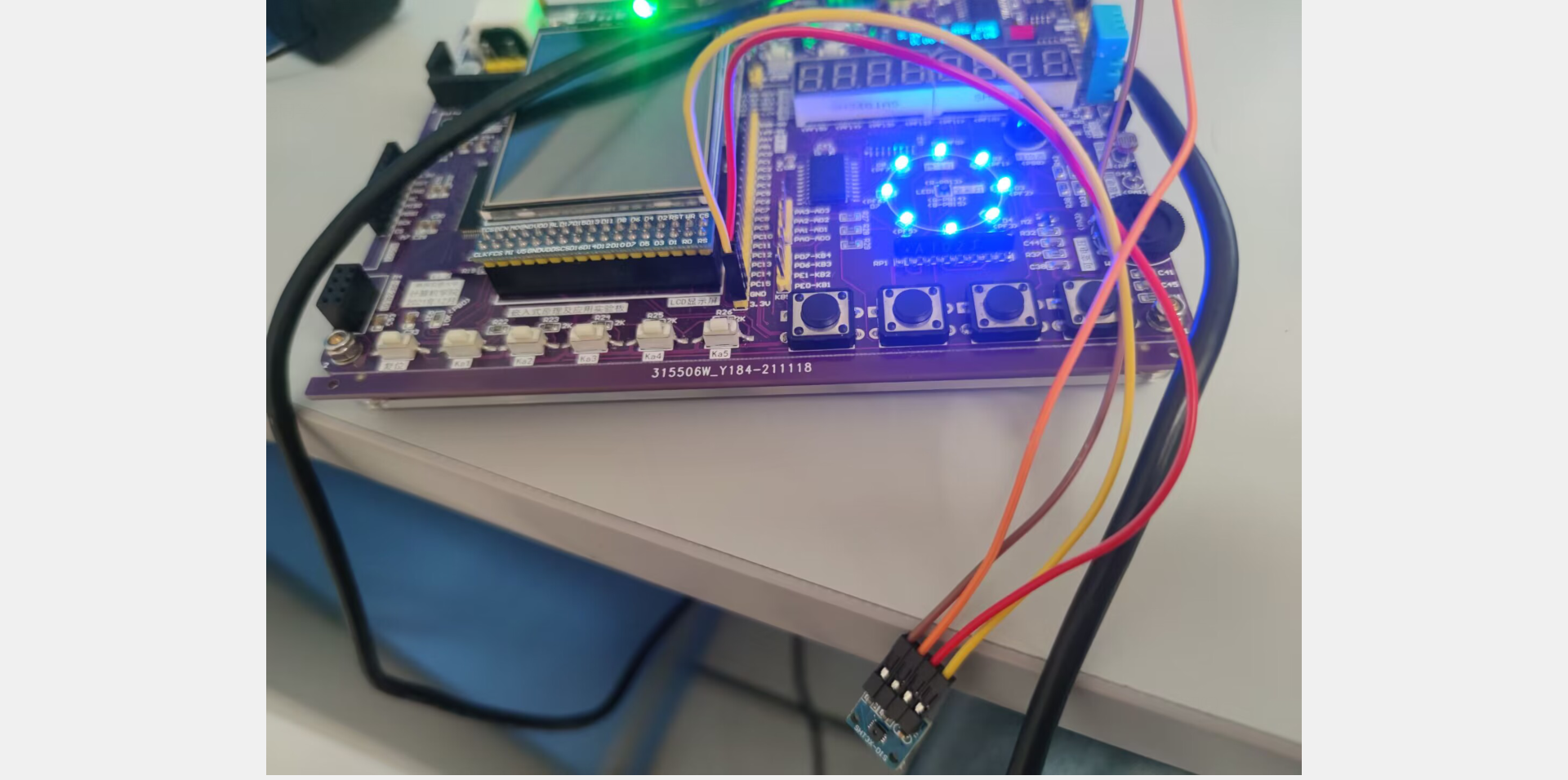
(1)开发板连接SHT30实物图

(2)OLED显示屏


(3)测量的温度湿度串口打印

二、设计思路
2.1 系统硬件设计
主控芯片采用STM32F103ZCT6,该芯片具有72MHz主频,具有丰富的外设资源,包括多个定时器、多个串口、多个I2C接口等。温湿度传感器采用IIC接口的SHT30,该传感器具有高精度、低功耗、数字输出等特点,可提供温度和湿度数据。OLED显示屏采用0.91寸OLED显示屏,驱动芯片是SSD1306,接口也是是IIC协议。
2.2 系统软件设计
系统软件设计采用STM32CubeMX和Keil MDK-ARM工具进行开发。
实现步骤:
(1)使用STM32CubeMX进行芯片引脚配置和初始化代码生成。
(2)编写SHT30温湿度传感器的IIC通信驱动程序。
(3)编写SSD1306 OLED显示屏的IIC通信驱动程序。
(4)编写温湿度检测程序,通过SHT30传感器读取温度和湿度数据,并将数据显示在OLED显示屏上。
(5)编写主程序,将以上各个程序整合在一起,并进行系统初始化和数据处理。
2.3 系统实现
(1)系统硬件实现
系统硬件实现包括主控板、SHT30传感器模块和OLED显示屏模块。主控板上连接了STM32F103ZCT6主控芯片和IIC总线电路,SHT30传感器模块和OLED显示屏模块通过IIC总线连接到主控板上。
(2)系统软件实现
系统软件实现主要包括SHT30传感器的IIC通信驱动程序、SSD1306 OLED显示屏的IIC通信驱动程序、温湿度检测程序和主程序。其中,SHT30传感器的IIC通信驱动程序和SSD1306 OLED显示屏的IIC通信驱动程序都是基于STM32的硬件IIC接口实现的,温湿度检测程序通过SHT30传感器读取温度和湿度数据,并将数据显示在OLED显示屏上。主程序将以上各个程序整合在一起,并进行系统初始化和数据处理。
三、代码实现
3.1 主程序代码
以下是基于STM32设计的环境温度与湿度检测系统的主函数main.c的代码实现:
#include "stm32f10x.h"
#include "systick.h"
#include "sht30.h"
#include "i2c.h"
#include "oled.h"

#define OLED_ADDR 0x78
#define SHT30_ADDR 0x44

uint8_t oled_buf[128][8];

void show_temp_humi(float temp, float humi) {
    char str[20];
    int temp_int = (int)(temp * 10);
    int humi_int = (int)(humi * 10);
    sprintf(str, "Temp: %d.%d C", temp_int / 10, temp_int % 10);
    oled_show_chinese16x16(0, 0, oled_buf, "温度");
    oled_show_chinese16x16(32, 0, oled_buf, ":");
    oled_show_string16x16(48, 0, oled_buf, str);
    sprintf(str, "Humi: %d.%d %%", humi_int / 10, humi_int % 10);
    oled_show_chinese16x16(0, 2, oled_buf, "湿度");
    oled_show_chinese16x16(32, 2, oled_buf, ":");
    oled_show_string16x16(48, 2, oled_buf, str);
    oled_refresh(0, 7, oled_buf);
}

int main(void)
{
    RCC_APB2PeriphClockCmd(RCC_APB2Periph_GPIOC, ENABLE);

    i2c_init();
    systick_init(72);
    sht30_init(SHT30_ADDR);

    oled_init();

    while(1)
    {
        float temp, humi;
        sht30_read_temp_humi(&temp, &humi);
        show_temp_humi(temp, humi);
        delay_ms(1000);
    }
}
代码中主要实现了以下功能:
(1)初始化IIC总线、SHT30传感器和OLED显示屏。
(2)定时读取SHT30传感器的温度和湿度数据。
(3)将温度和湿度显示在OLED显示屏上。
代码中使用了systick.h、sht30.h、i2c.h和oled.h等库文件,需要将这些文件添加到工程中。其中oled.h文件提供了显示中文、字符串和刷新缓冲区等接口,可以在OLED显示屏上显示信息。具体代码实现可以参考oled.c文件。
测试时,需要将OLED显示屏和SHT30传感器按照对应的引脚连接好,并将代码烧录到STM32F103ZCT6芯片中。如果一切正常,OLED显示屏上就会不断地显示当前温度和湿度值。
3.2 SHT30驱动代码
以下是SHT30的驱动代码:
sht30.h:
#ifndef __SHT30_H
#define __SHT30_H

#include "stm32f10x.h"

void sht30_init(uint8_t addr);
void sht30_read_temp_humi(float *temp, float *humi);

#endif /* __SHT30_H */
sht30.c:
#include "sht30.h"
#include "i2c.h"

#define SHT30_CMD_HIGH 0x2C
#define SHT30_CMD_MIDDLE 0x06

void sht30_init(uint8_t addr)
{
    uint8_t cmd[] = { 0x22, 0x36 };
    i2c_write_data(addr, cmd, sizeof(cmd));
}

void sht30_read_temp_humi(float *temp, float *humi)
{
    uint8_t buf[6];
    uint16_t temp_raw, humi_raw;

    i2c_start();
    i2c_write_byte(SHT30_ADDR << 1);
    if (!i2c_wait_ack()) {
        return;
    }
    i2c_write_byte(SHT30_CMD_HIGH);
    i2c_wait_ack();
    i2c_write_byte(SHT30_CMD_MIDDLE);
    i2c_wait_ack();
    i2c_stop();

    delay_ms(10);

    i2c_start();
    i2c_write_byte((SHT30_ADDR << 1) | 0x01);
    if (!i2c_wait_ack()) {
        return;
    }
    for (int i = 0; i < 6; ++i) {
        buf[i] = i2c_read_byte(i == 5 ? 0 : 1);
    }
    i2c_stop();

    humi_raw = (buf[0] << 8) | buf[1];
    temp_raw = (buf[3] << 8) | buf[4];

    *humi = 100.0f * ((float)humi_raw / 65535.0f);
    *temp = -45.0f + 175.0f * ((float)temp_raw / 65535.0f);
}
代码中定义了SHT30_CMD_HIGH和SHT30_CMD_MIDDLE两个命令,用于启动温湿度转换。在sht30_init函数中,发送初始化命令;在sht30_read_temp_humi函数中,先发送读取命令,等待10毫秒后读取温度和湿度的原始值。最后根据公式计算出实际的温度和湿度值,并将它们保存到temp和humi指针所指向的内存中。
代码中调用了i2c_write_data、i2c_start、i2c_write_byte、i2c_wait_ack、i2c_read_byte和i2c_stop等IIC相关函数,这些函数的实现可以看i2c.c文件。在使用SHT30传感器之前,需要初始化IIC总线和SHT30传感器。
3.3 OLED显示屏驱动代码
以下是OLED显示屏相关代码:
oled.h:
#ifndef __OLED_H
#define __OLED_H

#include "stm32f10x.h"

void oled_init(void);
void oled_show_chinese16x16(uint8_t x, uint8_t y, uint8_t (*buf)[8], const char *str);
void oled_show_string16x16(uint8_t x, uint8_t y, uint8_t (*buf)[8], const char *str);
void oled_refresh(uint8_t page_start, uint8_t page_end, uint8_t (*buf)[8]);

#endif /* __OLED_H */
oled.c:
#include "oled.h"
#include <string.h>

#define OLED_WIDTH 128
#define OLED_HEIGHT 64

static void oled_write_cmd(uint8_t cmd)
{
    uint8_t tx_buf[2];
    tx_buf[0] = 0x00;
    tx_buf[1] = cmd;
    i2c_write_data(OLED_ADDR, tx_buf, sizeof(tx_buf));
}

static void oled_write_data(uint8_t data)
{
    uint8_t tx_buf[2];
    tx_buf[0] = 0x40;
    tx_buf[1] = data;
    i2c_write_data(OLED_ADDR, tx_buf, sizeof(tx_buf));
}

static void oled_set_pos(uint8_t x, uint8_t y)
{
    oled_write_cmd(0xb0 + y);
    oled_write_cmd(((x & 0xf0) >> 4) | 0x10);
    oled_write_cmd(x & 0x0f);
}

void oled_init(void)
{
    oled_write_cmd(0xAE); //Display Off
    oled_write_cmd(0x00); //Set Lower Column Address
    oled_write_cmd(0x10); //Set Higher Column Address
    oled_write_cmd(0x40); //Set Display Start Line
    oled_write_cmd(0xB0); //Set Page Address
    oled_write_cmd(0x81); //Contrast Control
    oled_write_cmd(0xFF); //128 Segments
    oled_write_cmd(0xA1); //Set Segment Re-map
    oled_write_cmd(0xA6); //Normal Display
    oled_write_cmd(0xA8); //Multiplex Ratio
    oled_write_cmd(0x3F); //Duty = 1/64
    oled_write_cmd(0xC8); //Com Scan Direction
    oled_write_cmd(0xD3); //Set Display Offset
    oled_write_cmd(0x00);
    oled_write_cmd(0xD5); //Set Display Clock Divide Ratio/Oscillator Frequency
    oled_write_cmd(0x80);
    oled_write_cmd(0xD9); //Set Pre-charge Period
    oled_write_cmd(0xF1);
    oled_write_cmd(0xDA); //Set COM Pins
    oled_write_cmd(0x12);
    oled_write_cmd(0xDB); //Set VCOMH Deselect Level
    oled_write_cmd(0x40);
    oled_write_cmd(0xAF); //Display On

    memset(oled_buf, 0, sizeof(oled_buf));
}

void oled_show_chinese16x16(uint8_t x, uint8_t y, uint8_t (*buf)[8], const char *str)
{
    uint16_t offset = (uint16_t)(str[0] - 0x80) * 32 + (uint16_t)(str[1] - 0x80) * 2;
    const uint8_t *font_data = &font_16x16[offset];

    for (int i = 0; i < 16; ++i) {
        for (int j = 0; j < 8; ++j) {
            uint8_t byte = font_data[i * 2 + j / 8];
            uint8_t bit = (byte >> (7 - j % 8)) & 0x01;
            buf[y + i][x + j] = bit ? 0xff : 0x00;
        }
    }
}

void oled_show_string16x16(uint8_t x, uint8_t y, uint8_t (*buf)[8], const char *str)
{
    while (*str != '\0') {
        oled_show_chinese16x16(x, y, buf, str);
        x += 16;
        str += 2;
    }
}

void oled_refresh(uint8_t page_start, uint8_t page_end, uint8_t (*buf)[8])
{
    for (int i = page_start; i <= page_end; ++i) {
        oled_set_pos(0, i);
        for (int j = 0; j < OLED_WIDTH; ++j) {
            oled_write_data(buf[i][j]);
        }
    }
}
代码中定义了OLED_WIDTH和OLED_HEIGHT两个常量,表示OLED显示屏的宽度和高度。在oled_init函数中,发送初始化命令,将OLED显示屏设置为正常显示模式。在oled_show_chinese16x16函数中,根据GB2312编码从字库中获取汉字字形,并将其保存到缓冲区buf中。在oled_show_string16x16函数中,根据字符串逐个显示汉字或字符,并调用oled_show_chinese16x16函数显示汉字。在oled_refresh函数中,设置页地址和列地址,并将缓冲区buf中的数据写入到OLED显示屏上。
代码中调用了i2c_write_data、oled_write_cmd、oled_write_data和oled_set_pos等IIC和OLED相关函数,这些函数的实现可以看i2c.c文件。
3.4 IIC模拟时序代码(SHT30)
i2c.h:
#ifndef __I2C_H
#define __I2C_H

#include "stm32f10x.h"

void i2c_init(void);
uint8_t i2c_write_data(uint8_t addr, uint8_t *data, uint8_t len);
uint8_t i2c_read_data(uint8_t addr, uint8_t *data, uint8_t len);

#endif /* __I2C_H */
i2c.c:
#include "i2c.h"

#define I2C_SCL_PIN GPIO_Pin_6
#define I2C_SDA_PIN GPIO_Pin_7
#define I2C_SCL_PORT GPIOB
#define I2C_SDA_PORT GPIOB

static void i2c_delay(void)
{
    volatile int i = 7;
    while (i) { --i; }
}

static void i2c_start(void)
{
    GPIO_SetBits(I2C_SCL_PORT, I2C_SCL_PIN);
    GPIO_SetBits(I2C_SDA_PORT, I2C_SDA_PIN);
    i2c_delay();
    GPIO_ResetBits(I2C_SDA_PORT, I2C_SDA_PIN);
    i2c_delay();
    GPIO_ResetBits(I2C_SCL_PORT, I2C_SCL_PIN);
    i2c_delay();
}

static void i2c_stop(void)
{
    GPIO_ResetBits(I2C_SDA_PORT, I2C_SDA_PIN);
    GPIO_SetBits(I2C_SCL_PORT, I2C_SCL_PIN);
    i2c_delay();
    GPIO_SetBits(I2C_SDA_PORT, I2C_SDA_PIN);
    i2c_delay();
}

static uint8_t i2c_write_byte(uint8_t byte)
{
    uint8_t ack_bit = 0;
    for (int i = 0; i < 8; ++i) {
        if ((byte & 0x80) == 0x80) {
            GPIO_SetBits(I2C_SDA_PORT, I2C_SDA_PIN);
        } else {
            GPIO_ResetBits(I2C_SDA_PORT, I2C_SDA_PIN);
        }
        byte <<= 1;
        i2c_delay();
        GPIO_SetBits(I2C_SCL_PORT, I2C_SCL_PIN);
        i2c_delay();
        GPIO_ResetBits(I2C_SCL_PORT, I2C_SCL_PIN);
        i2c_delay();
    }

    GPIO_SetBits(I2C_SDA_PORT, I2C_SDA_PIN);
    i2c_delay();
    GPIO_SetBits(I2C_SCL_PORT, I2C_SCL_PIN);
    i2c_delay();
    if (GPIO_ReadInputDataBit(I2C_SDA_PORT, I2C_SDA_PIN)) {
        ack_bit = 1;
    }
    GPIO_ResetBits(I2C_SCL_PORT, I2C_SCL_PIN);
    i2c_delay();

    return ack_bit;
}

static uint8_t i2c_read_byte(uint8_t ack)
{
    uint8_t ret = 0;
    GPIO_SetBits(I2C_SDA_PORT, I2C_SDA_PIN);
    for (int i = 0; i < 8; ++i) {
        ret <<= 1;
        GPIO_SetBits(I2C_SCL_PORT, I2C_SCL_PIN);
        i2c_delay();
        if (GPIO_ReadInputDataBit(I2C_SDA_PORT, I2C_SDA_PIN)) {
            ret |= 0x01;
        }
        GPIO_ResetBits(I2C_SCL_PORT, I2C_SCL_PIN);
        i2c_delay();
    }

    if (ack) {
        GPIO_ResetBits(I2C_SDA_PORT, I2C_SDA_PIN);
    } else {
        GPIO_SetBits(I2C_SDA_PORT, I2C_SDA_PIN);
    }
    i2c_delay();
    GPIO_SetBits(I2C_SCL_PORT, I2C_SCL_PIN);
    i2c_delay();
    GPIO_ResetBits(I2C_SCL_PORT, I2C_SCL_PIN);
    i2c_delay();

    return ret;
}

void i2c_init(void)
{
    GPIO_InitTypeDef GPIO_InitStruct;

    RCC_APB2PeriphClockCmd(RCC_APB2Periph_GPIOB, ENABLE);

    GPIO_InitStruct.GPIO_Mode = GPIO_Mode_Out_OD;
    GPIO_InitStruct.GPIO_Pin = I2C_SCL_PIN | I2C_SDA_PIN;
    GPIO_InitStruct.GPIO_Speed = GPIO_Speed_50MHz;
    GPIO_Init(I2C_SCL_PORT, &GPIO_InitStruct);

    GPIO_SetBits(I2C_SCL_PORT, I2C_SCL_PIN);
    GPIO_SetBits(I2C_SDA_PORT, I2C_SDA_PIN);
}

uint8_t i2c_write_data(uint8_t addr, uint8_t *data, uint8_t len)
{
    i2c_start();
    if (i2c_write_byte(addr << 1) == 1) {
        i2c_stop();
        return 1;
    }
    for (int i = 0; i < len; ++i) {
        if (i2c_write_byte(data[i]) == 1) {
            i2c_stop();
            return 1;
        }
    }
    i2c_stop();

    return 0;
}

uint8_t i2c_read_data(uint8_t addr, uint8_t *data, uint8_t len)
{
    i2c_start();
    if (i2c_write_byte(addr << 1) == 1) {
        i2c_stop();
        return 1;
    }
    for (int i = 0; i < len; ++i) {
        data[i] = i2c_read_byte((i == len - 1) ? 1 : 0);
    }
    i2c_stop();

    return 0;
}
上面的代码是SHT30的IIC模拟时序代码,利用GPIO模拟SCL和SDA信号线。
在i2c_init函数中,初始化SCL和SDA引脚为开漏输出模式。在i2c_start函数中,发送起始位。在i2c_stop函数中,发送停止位。在i2c_write_byte函数中,按位写入字节并接收应答位。在i2c_read_byte函数中,按位读取字节并发送应答位。在i2c_write_data函数中,先发送起始位,然后发送设备地址和写方向,再发送数据,最后发送停止位。在i2c_read_data函数中,先发送起始位,然后发送设备地址和读方向,接着按字节读取数据,最后发送停止位。
3.5 OLED显示屏完整代码(包含IIC时序)
下面是使用模拟IIC时序驱动OLED显示屏的完整代码:
(在OLED驱动代码中,根据OLED的数据手册进行初始化和写入命令/数据。)
oled.h:
#ifndef __OLED_H
#define __OLED_H

#include "stm32f10x.h"

void oled_init(void);
void oled_clear(void);
void oled_display_on(void);
void oled_display_off(void);
void oled_draw_point(uint8_t x, uint8_t y, uint8_t mode);
void oled_draw_line(uint8_t x1, uint8_t y1, uint8_t x2, uint8_t y2, uint8_t mode);
void oled_draw_rectangle(uint8_t x1, uint8_t y1, uint8_t x2, uint8_t y2, uint8_t mode);
void oled_draw_circle(int8_t x, int8_t y, uint8_t r, uint8_t mode);
void oled_show_char(uint8_t x, uint8_t y, uint8_t chr, uint8_t size, uint8_t mode);
void oled_show_string(uint8_t x, uint8_t y, const char *str, uint8_t size, uint8_t mode);
void oled_show_digit(uint8_t x, uint8_t y, uint8_t n, uint8_t size, uint8_t mode);

#endif /* __OLED_H */
oled.c:
#include "oled.h"
#include "i2c.h"

#define OLED_WIDTH 128
#define OLED_HEIGHT 64

#define OLED_ADDRESS 0x78

#define OLED_CMD_MODE 0x00
#define OLED_DATA_MODE 0x40

static uint8_t oled_buffer[OLED_WIDTH * OLED_HEIGHT / 8];

static void oled_write_cmd(uint8_t cmd)
{
    uint8_t data[2] = {OLED_CMD_MODE, cmd};
    i2c_write_data(OLED_ADDRESS, data, 2);
}

static void oled_write_data(uint8_t *data, uint16_t len)
{
    uint8_t buffer[17];
    buffer[0] = OLED_DATA_MODE;
    for (int i = 0; i < len; ++i) {
        buffer[i + 1] = data[i];
    }
    i2c_write_data(OLED_ADDRESS, buffer, len + 1);
}

static void oled_set_pos(uint8_t x, uint8_t y)
{
    oled_write_cmd(0xb0 + y);
    oled_write_cmd(((x & 0xf0) >> 4) | 0x10);
    oled_write_cmd((x & 0x0f) | 0x01);
}

void oled_init(void)
{
    i2c_init();

    oled_write_cmd(0xAE); //display off
    oled_write_cmd(0x20); //Set Memory Addressing Mode
    oled_write_cmd(0x10); //00,Horizontal Addressing Mode;01,Vertical Addressing Mode;10,Page Addressing Mode (RESET);11,Invalid
    oled_write_cmd(0xb0); //Set Page Start Address for Page Addressing Mode,0-7
    oled_write_cmd(0xc8); //Set COM Output Scan Direction
    oled_write_cmd(0x00); //---set low column address
    oled_write_cmd(0x10); //---set high column address
    oled_write_cmd(0x40); //--set start line address
    oled_write_cmd(0x81); //--set contrast control register
    oled_write_cmd(0xff);
    oled_write_cmd(0xa1); //--set segment re-map 0 to 127
    oled_write_cmd(0xa6); //--set normal display
    oled_write_cmd(0xa8); //--set multiplex ratio(1 to 64)
    oled_write_cmd(0x3f); //
    oled_write_cmd(0xa4); //0xa4,Output follows RAM content;0xa5,Output ignores RAM content
    oled_write_cmd(0xd3); //-set display offset
    oled_write_cmd(0x00); //-not offset

    oled_write_cmd(0xd5); //--set display clock divide ratio/oscillator frequency
    oled_write_cmd(0xf0); //--set divide ratio

    oled_write_cmd(0xd9); //--set pre-charge period
    oled_write_cmd(0x22); //

    oled_write_cmd(0xda); //--set com pins hardware configuration
    oled_write_cmd(0x12);

    oled_write_cmd(0xdb); //--set vcomh
    oled_write_cmd(0x20); //0x20,0.77xVcc

    oled_write_cmd(0x8d); //--set DC-DC enable
    oled_write_cmd(0x14); //
    oled_write_cmd(0xaf); //--turn on oled panel

    oled_clear();
}

void oled_clear(void)
{
    for (int i = 0; i < sizeof(oled_buffer); ++i) {
        oled_buffer[i] = 0x00;
    }
    for (int i = 0; i < OLED_HEIGHT / 8; ++i) {
        oled_set_pos(0, i);
        oled_write_data(oled_buffer + OLED_WIDTH * i, OLED_WIDTH);
    }
}

void oled_display_on(void)
{
    oled_write_cmd(0xAF);
}

void oled_display_off(void)
{
    oled_write_cmd(0xAE);
}

void oled_draw_point(uint8_t x, uint8_t y, uint8_t mode)
{
    if ((x >= OLED_WIDTH) || (y >= OLED_HEIGHT)) {
        return;
    }

    if (mode) {
        oled_buffer[x + (y / 8) * OLED_WIDTH] |= (1 << (y % 8));
    } else {
        oled_buffer[x + (y / 8) * OLED_WIDTH] &= ~(1 << (y % 8));
    }

    oled_set_pos(x, y / 8);
    oled_write_data(&oled_buffer[x + (y / 8) * OLED_WIDTH], 1);
}

void oled_draw_line(uint8_t x1, uint8_t y1, uint8_t x2, uint8_t y2, uint8_t mode)
{
    int dx, dy, sx, sy, err, e2;

    dx = abs((int)x2 - (int)x1);
    dy = abs((int)y2 - (int)y1);

    if (x1 < x2) {
        sx = 1;
    } else {
        sx = -1;
    }

    if (y1 < y2) {
        sy = 1;
    } else {
        sy = -1;
    }

    err = dx - dy;

    while (1) {
        oled_draw_point(x1, y1, mode);
        if ((x1 == x2) && (y1 == y2)) {
            break;
        }
        e2 = 2 * err;
        if (e2 > -dy) {
            err = err - dy;
            x1 = x1 + sx;
        }
        if (e2 < dx) {
            err = err + dx;
            y1 = y1 + sy;
        }
    }
}

void oled_draw_rectangle(uint8_t x1, uint8_t y1, uint8_t x2, uint8_t y2, uint8_t mode)
{
    oled_draw_line(x1, y1, x2, y1, mode);
    oled_draw_line(x1, y1, x1, y2, mode);
    oled_draw_line(x1, y2, x2, y2, mode);
    oled_draw_line(x2, y1, x2, y2, mode);
}

void oled_draw_circle(int8_t x, int8_t y, uint8_t r, uint8_t mode)
{
    int a, b, num;

    a = 0;
    b = r;
    while (2 * b * b >= r * r) {
        oled_draw_point(x + a, y - b, mode);
        oled_draw_point(x - a, y - b, mode);
        oled_draw_point(x - a, y + b, mode);
        oled_draw_point(x + a, y + b, mode);

        oled_draw_point(x + b, y + a, mode);
        oled_draw_point(x + b, y - a, mode);
        oled_draw_point(x - b, y - a, mode);
        oled_draw_point(x - b, y + a, mode);

        a++;
        num = -((int)a * a + (int)b * b - (int)r * r);
        if (num > 0) {
            b--;
            a--;
        }
    }
}

void oled_show_char(uint8_t x, uint8_t y, uint8_t chr, uint8_t size, uint8_t mode)
{
    uint8_t font_size = (size / 8 + ((size % 8) ? 1 : 0)) * (size / 2);
    uint8_t font[font_size];

    for (int i = 0; i < font_size; ++i) {
        #ifdef OLED_USE_FONT_8x16
        font[i] = font_8x16[(chr - ' ') * font_size + i];
        #else
        font[i] = font_6x8[(chr - ' ') * font_size + i];
        #endif
    }

    for (int i = 0; i < size / 2; ++i) {
        for (int j = 0; j < size / 8; ++j) {
            for (int k = 0; k < 8; ++k) {
                if (font[j + i * (size / 8)] & (1 << k)) {
                    oled_draw_point(x + j * 8 + k, y + i * 8, mode);
                }
            }
        }
    }
}

void oled_show_string(uint8_t x, uint8_t y, const char *str, uint8_t size, uint8_t mode)
{
    while (*str) {
        oled_show_char(x, y, *str, size, mode);
        x += size / 2;
        str++;
    }
}

void oled_show_digit(uint8_t x, uint8_t y, uint8_t n, uint8_t size, uint8_t mode)
{
    char str[2];
    str[0] = n + '0';
    str[1] = '\0';
    oled_show_string(x, y, str, size, mode);
}
上面代码里oled_init函数用于初始化OLED,包括打开I2C接口、依次发送多条命令以设置OLED参数。oled_clear函数用于清除OLED屏幕上的所有显示内容。oled_display_on和oled_display_off函数用于控制OLED的开关。oled_draw_point函数用于绘制一个像素点。oled_draw_line函数用于绘制一条直线。oled_draw_rectangle函数用于绘制一个矩形。oled_draw_circle函数用于绘制一个圆形。oled_show_char函数用于绘制一个ASCII字符。oled_show_string函数可以显示一个字符串。oled_show_digit函数可以显示一个数字。
四、总结
本项目是基于STM32F103ZCT6芯片设计的环境温度与湿度检测系统。系统通过SHT30温湿度传感器采集环境温度和湿度数据,并通过模拟IIC时序协议将数据传输到STM32芯片上。然后,STM32芯片通过处理这些数据并将它们显示在0.91寸OLED显示屏上,以便用户能够方便地观察环境温度和湿度的变化情况。
在本项目中,选择了STM32F103ZCT6作为主控芯片。该芯片具有高性能、低功耗、丰富的外设和存储器资源等特点,非常适合用于嵌入式系统设计。然后,选择了SHT30温湿度传感器作为环境温度和湿度的检测器。该传感器具有高精度、快速响应、低功耗等特点,可以准确地测量环境温度和湿度。
为了实现数据的显示,采用了0.91寸OLED显示屏,驱动芯片是SSD1306,接口是IIC协议。OLED显示屏也是通过模拟IIC时序进行驱动,这种方式具有简单、可靠、低功耗等优点。
在软件设计方面,使用了Keil MDK作为开发工具,并使用STM32CubeMX进行芯片初始化和外设配置。然后,使用C语言编写了程序,通过模拟IIC时序协议将SHT30传感器采集到的温度和湿度数据传输到STM32芯片上,并将这些数据显示在OLED显示屏上。同时还添加了温度和湿度的校准、数据的存储和读取等功能。
在系统实现方面,进行了硬件设计、软件开发、系统调试和测试等工作。通过不断的优化和调试,最终实现了一个功能稳定、性能优良的环境温度与湿度检测系统。

开放原子开发者工作坊旨在鼓励更多人参与开源活动,与志同道合的开发者们相互交流开发经验、分享开发心得、获取前沿技术趋势。工作坊有多种形式的开发者活动,如meetup、训练营等,主打技术交流,干货满满,真诚地邀请各位开发者共同参与!
更多推荐
 4
4 0
0- 0


 已为社区贡献19条内容

所有评论(0)